How DC Block Configuration Affects Land Usage on a 25 MWh BESS Site
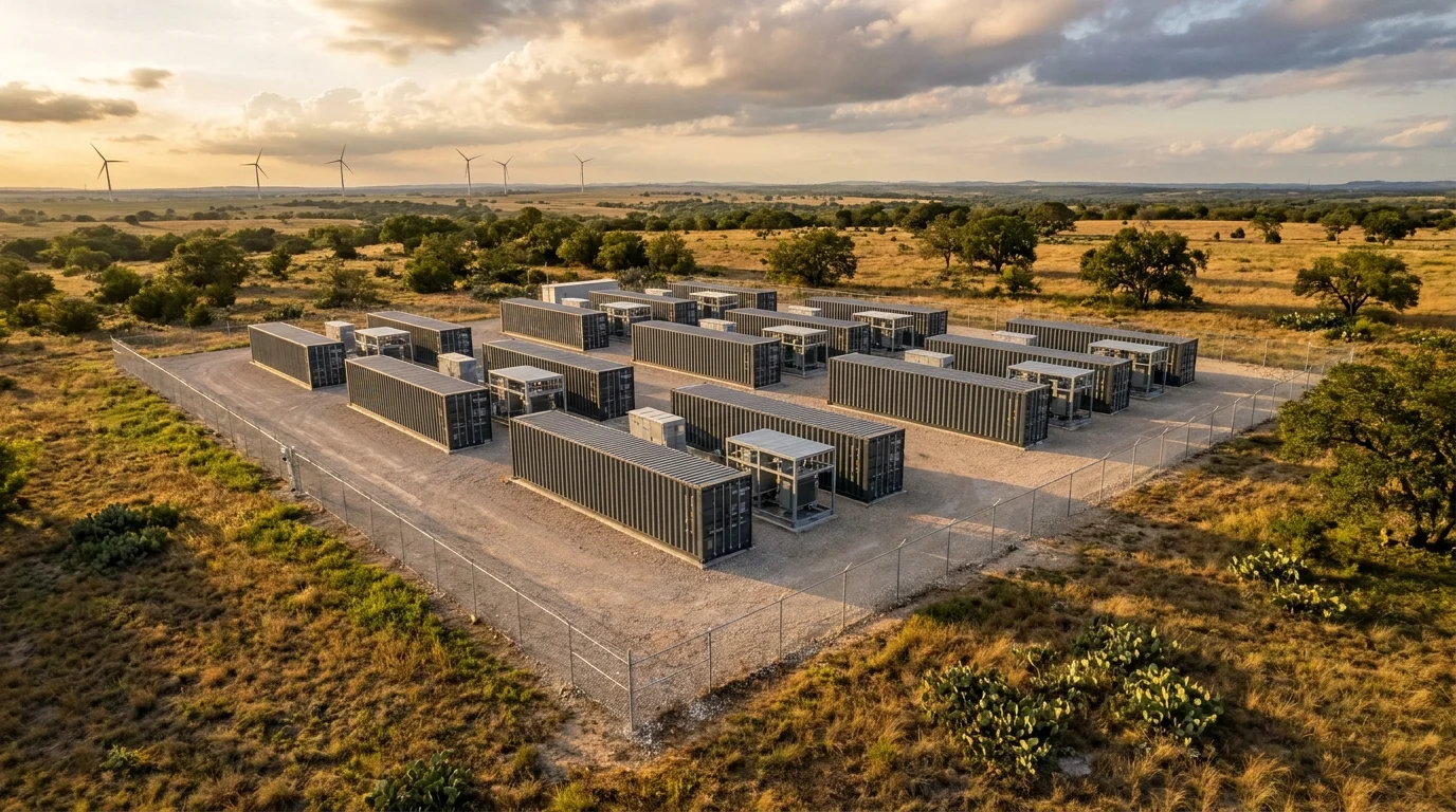
A 25 MWh BESS plant with four DC blocks can be arranged in several configurations — solo, twin, or quad. Each uses a different amount of land. The configuration that looks most compact does not produce the smallest footprint — not at the DC block level and not when the PCS & MV skid is added.
The Reference Site
This comparison uses a 25 MWh, 2-hour BESS plant. The equipment consists of four DC blocks at 6.25 MWh each, connected to one 40 ft PCS and MV skid. This is a common architecture for a single BESS section.
The comparison starts with DC block arrangements alone, then adds the PCS and MV skid to show how the full equipment set changes the result.
Service Clearance
Every piece of equipment on a BESS plant site requires service clearance — unobstructed space that must remain accessible for maintenance, inspection, and component replacement. Technicians need room to open container doors, wheel out battery modules, swap PCS modules, and position lifting equipment. If the clearance on a DC block's door side is insufficient, it cannot be serviced without moving adjacent equipment — a costly and sometimes structurally impossible operation.
Service clearance is not fire safety separation distance. Separation distance is the space between equipment required to prevent fire propagation. Service clearance is the space needed to physically access and work on the equipment.
For a typical DC block, the service clearance requirements are:
- 3 meters on the door side (long side) — for primary maintenance access
- 2 meters on the cable side (short side) — for cable termination, HVAC cooling unit access, and sufficient airflow
- Blind sides — the remaining long and short sides have no access points and require no service clearance
Blind sides are what make stacking possible. Two DC blocks can be placed with their blind sides facing each other, separated by only a fire safety gap. No service clearance is needed between them because there is nothing to access on those walls.
The PCS and MV skid also require service clearance — typically 3 meters on all sides — for both maintenance access and sufficient airflow for cooling.
Four DC Block Configurations
DC blocks are arranged in four standard configurations:
Solo — each DC block stands alone with its own independent service clearances.
Twin Long — two DC blocks placed side by side along their long edge, blind long sides facing each other.
Twin Short — two DC blocks placed side by side along their short edge, blind short sides facing each other.
Quad — four DC blocks in a 2×2 formation, sharing blind sides in both directions.
In twin and quad configurations, the gap between adjacent DC blocks is typically 0.2 to 0.5 meters — a fire safety distance to prevent block-to-block propagation.
DC Block Footprint Only
When only DC blocks are considered, the result is counter-intuitive. Most people assume that packing DC blocks tightly together — as in a quad — would use the least land. In practice, the opposite is true. Four solo blocks can be arranged so their door sides and cable ends face each other, sharing service clearance corridors between them. The clearance that one block needs on its door side doubles as the clearance for the block facing it. Twin short works the same way — the pairs face each other and share the space between them.
In quad, the blocks are physically closer together, but their clearances wrap around the outside of the cluster with no opportunity to share. The total footprint is the largest of all four configurations.
Adding the PCS and MV Skid
When the PCS and MV skid is added, its placement relative to the DC blocks changes the total footprint. The skid requires 3 meters of service clearance on all sides. Whether those zones overlap with existing DC block clearances — or add new land — depends on the configuration.
Skid between the rows
In solo and twin short configurations, the DC blocks form two rows with space between them. The PCS and MV skid fits in this center space, adjacent to DC block door sides on both sides. The 3-meter clearance for the skid and the 3-meter clearance for the DC block doors occupy the same zone — a single access corridor serves both.
Skid beside the stack
In twin long and quad configurations, the DC blocks form a compact cluster with no room for the skid between rows. The skid is placed beside the cluster instead. Only one side faces DC block doors, so only one clearance zone is shared. The opposite side faces open ground and requires its own dedicated clearance — additional land that does not overlap with any DC block service area.
The Footprint Comparison
For the 25 MWh reference site:
| Configuration | Footprint | Dimensions | Skid placement |
|---|---|---|---|
| Solo | 242 m² | 18.2 × 13.3 m | Between the rows |
| Twin Short | 242 m² | 18.2 × 13.3 m | Between the pairs |
| Twin Long | 300 m² | 18.2 × 16.5 m | Beside the stack |
| Quad | 300 m² | 18.2 × 16.5 m | Beside the stack |
Solo and twin short use 19% less land than twin long and quad — same energy capacity, same equipment, different arrangement.
In energy density terms:
- Solo and Twin Short: 103 kWh/m²
- Twin Long and Quad: 83 kWh/m²
Why Tighter Stacking Uses More Land
The intuition that packing DC blocks tightly together saves land is wrong. In a quad arrangement, the four blocks sit close together — but every exterior side of the cluster requires its own clearance zone. No clearance is shared between the quad and any adjacent equipment.
In solo and twin short, the blocks are spaced further apart, but that spacing is not wasted. The gap between the rows becomes a shared access corridor — the same 3 meters serves the DC block doors on one side and the skid on the other. The skid slots into space that already existed for DC block maintenance.
In twin long and quad, the cluster is too deep to fit the skid between rows. The skid goes beside the cluster, and its clearance extends the footprint outward without overlapping anything.
The 19% difference in land usage comes entirely from this geometric effect. The only variable is whether the service clearance zones overlap or stack.
Try it yourselfDesign your BESS site layoutPlace DC blocks, set safety distances, and export your layout — free, sign up in seconds.Open the layout tool →